
Signal Generator
1435A/B-V Series Signal Generator
Frequency rang
9 kHz ~ 6 GHz
Internal modulated signal generator frequency
10 MHz
Minimum pulse width
20 ns
Single-sideband phase noise
(10 GHz carrier @ 10 kHz frequency offset)
-136 dBc/Hz
Maximum output power Internal modulation bandwidth
22 dBm@3 GHz 200 MHz
Technical Specifications
| Frequency Characteristic |
||||||||||||||||||||
| Frequency Range | 1435A-V: 9 kHz~3 GHz 1435B-V: 9 kHz~6 GHz |
Frequency | N(Number of fundamental harmonics) |
|||||||||||||||||
| 9 kHz ≤ f < 250 MHz |
1/4 |
|||||||||||||||||||
| 250 MHz ≤ f ≤ 375 MHz |
1/16 |
|||||||||||||||||||
| 375 MHz < f ≤ 750 MHz |
1/8 |
|||||||||||||||||||
| 750 MHz < f ≤ 1.5 GHz |
1/4 |
|||||||||||||||||||
| 1.5 GHz < f ≤ 3 GHz |
1/2 |
|||||||||||||||||||
| 3 GHz < f ≤ 6 GHz |
1 |
|||||||||||||||||||
| Frequency Resolution | 0.001 Hz |
|||||||||||||||||||
| Frequency Switching Time | ≤ 1 ms ( typical value ) |
|||||||||||||||||||
| Time-based Aging Rate (typical) |
Standard Configuration: ±5×10 -7 /Years (after 30 days of continuous energization) Highly Stable Time Base Option H10: ±5×10 -8 /Years (after 30 days of continuous energization) ±5×10 -10 /Years (after 30 days of continuous energization) |
|||||||||||||||||||
| Reference Output | Frequency | 10 MHz |
||||||||||||||||||
| Power |
> +4 dBm, To 50Ω load |
|||||||||||||||||||
| Reference Input | Frequency | 1 MHz ~ 50 MHz, Step 1 Hz |
||||||||||||||||||
| Power |
0 dBm ~ +7 dBm, To 50Ω load |
|||||||||||||||||||
| Scanning Characteristics |
||||||||||||||||||||
| Scanning Mode | Step Scan, List Scan | |||||||||||||||||||
| Scanning Dwell Time | 100 μs ~ 100 s |
|||||||||||||||||||
| Power Characteristics |
||||||||||||||||||||
| Minimum Power | Standard Configuration | Option H01 |
||||||||||||||||||
| -15 dBm ( Settable -20 dBm) |
-110 dBm ( Settable -135 dBm) |
|||||||||||||||||||
| Maximum Power (25±10 °C) |
Frequency Range | Standard Configuration | High Power Output Option H08 |
|||||||||||||||||
| 9 kHz ≤ f ≤ 3 GHz |
18 dBm |
22 dBm |
||||||||||||||||||
| 3 GHz < f ≤ 5 GHz |
16 dBm |
20 dBm |
||||||||||||||||||
| 5 GHz < f ≤ 6 GHz |
15 dBm |
18 dBm |
||||||||||||||||||
| Power Accuracy (25±10 °C) |
Standard Configuration | |||||||||||||||||||
| Frequency ↓ Power( dBm)→ |
10 ~ maximum power |
-10 ~ 10 |
-15 ~ -10 |
|||||||||||||||||
| 9 kHz ≤ f ≤ 2 GHz |
±0.8 dB |
±0.6 dB |
±1.5 dB |
|||||||||||||||||
| 2 GHz < f ≤ 6 GHz |
±0.9 dB |
±0.7 dB |
±1.5 dB |
|||||||||||||||||
| H01 Programmable Step Attenuator Option |
||||||||||||||||||||
| Frequency ↓ Power( dBm)→ | 10 ~ maximum power |
-10 ~ 10 |
-70 ~ -10 |
-90 ~ -70 |
||||||||||||||||
| 9 kHz ≤ f ≤ 2 GHz |
±0.8 dB |
±0.6 dB |
±0.7 dB |
±1.4 dB |
||||||||||||||||
| 2 GHz < f ≤ 6 GHz |
±0.9 dB |
±0.7 dB |
±0.7 dB |
±1.6 dB |
||||||||||||||||
| Power Resolution | 0.01 dB |
|||||||||||||||||||
| Output Impedance | 50 Ω (rated value) |
|||||||||||||||||||
| Source VSWR (internal stabilized amplitude) (typical) |
9 kHz ≤ f ≤ 3 GHz |
< 1.7 |
||||||||||||||||||
| 3 GHz < f ≤ 6 GHz |
< 1.6 |
|||||||||||||||||||
| Maximum reverse power | 0.5 W(0 V DC)( rated value ) |
|||||||||||||||||||
| Spectrum Purity |
||||||||||||||||||||
| Harmonics (at +10 dBm) |
Frequency | Standard Configuration | ||||||||||||||||||
| 9 kHz ≤ f ≤ 10 MHz |
< -23 dBc |
|||||||||||||||||||
| 10 MHz < f ≤ 2 GHz |
< -30 dBc |
|||||||||||||||||||
| 2 GHz < f ≤ 3 GHz(1435A-V) |
< -55 dBc |
|||||||||||||||||||
| 2 GHz < f ≤ 6 GHz(1435B-V) |
< -30 dBc |
|||||||||||||||||||
| Subharmonic (at +10 dBm) |
9 kHz ≤ f ≤ 6 GHz |
N/A |
||||||||||||||||||
| Non-harmonic (at 0 dBm, 10 kHz frequency offset away) |
Frequency | Standard Configuration | Low phase noise option | |||||||||||||||||
| 9 kHz ≤ f < 250 MHz |
< -54 dBc |
< -58 dBc |
||||||||||||||||||
| 250 MHz ≤ f ≤ 3 GHz |
< -62 dBc |
< -77 dBc |
||||||||||||||||||
| 3 GHz < f ≤ 6 GHz |
< -56 dBc |
< -71 dBc |
||||||||||||||||||
| Single Sideband Phase Noise ( dBc/Hz at +10 dBm) |
Standard Configuration | |||||||||||||||||||
| Frequency | 100Hz |
10 kHz |
||||||||||||||||||
| 100 MHz |
-83 |
-115 |
||||||||||||||||||
| 250 MHz |
-93 |
-127 |
||||||||||||||||||
| 500 MHz |
-89 |
-121 |
||||||||||||||||||
| 1 GHz |
-83 |
-115 |
||||||||||||||||||
| 2 GHz |
-77 |
-109 |
||||||||||||||||||
| 3 GHz |
-74 |
-105 |
||||||||||||||||||
| 4 GHz |
-71 |
-103 |
||||||||||||||||||
| 6 GHz |
-68 |
-99 |
||||||||||||||||||
| Low phase noise option H06 |
||||||||||||||||||||
| Frequency | 100Hz |
1 kHz |
10 kHz |
100 kHz |
||||||||||||||||
| 100 MHz |
-83 |
-112 |
-131 |
-131 |
||||||||||||||||
| 250 MHz |
-93 |
-123 |
-139 |
-139 |
||||||||||||||||
| 500 MHz |
-89 |
-119 |
-135 |
-135 |
||||||||||||||||
| 1 GHz |
-83 |
-113 |
-132 |
-132 |
||||||||||||||||
| 2 GHz |
-77 |
-107 |
-126 |
-126 |
||||||||||||||||
| 3 GHz |
-74 |
-104 |
-121 |
-121 |
||||||||||||||||
| 4 GHz |
-71 |
-101 |
-120 |
-120 |
||||||||||||||||
| 6 GHz |
-68 |
-98 |
-115 |
-115 |
||||||||||||||||
| Modulation Characteristics |
||||||||||||||||||||
| Frequency Modulation (Option H02) |
Maximum frequency deviation: N×16 MHz (N is the number of fundamental harmonics) Accuracy (1 kHz modulation rate, frequency offset N×500 kHz): ±(2%×set frequency offset+20Hz) Modulation rate (3 dB bandwidth, frequency offset N x 500 kHz): DC-7 MHz Distortion (1 kHz rate, Bias N x 500 kHz): <0.4% |
|||||||||||||||||||
| Phase Modulation (Option H02) |
Maximum phase deviation: N×16rad (N is the number of fundamental harmonics) Accuracy (1 kHz modulation rate, phase shift N×8rad): ±(2%×set phase shift+0.01rad) Modulation rate (3 dB bandwidth, phase bias N x 8rad): DC-1 MHz Distortion (1 kHz modulation rate, phase bias N x 8 rad): < 0.4% |
|||||||||||||||||||
| Amplitude Modulation (Option H02) |
Maximum depth: > 90% AM accuracy: (1 kHz modulation rate, 30% modulation depth): ±(4%×set depth+1%) AM distortion: (1 kHz modulation rate, linear mode, THD, 30% modulation depth): < 2%. AM bandwidth (3 dB bandwidth, 30% modulation depth, frequency test points: 1 GHz, 5 GHz): DC ~ 100 kHz. |
|||||||||||||||||||
| Pulse modulation (Option H03) |
Switching Ratio | > 80 dB |
||||||||||||||||||
| Rise and fall time | < 10ns |
|||||||||||||||||||
| Minimum pulse width for internal stabilization amplitude | 1μs |
|||||||||||||||||||
| Minimum pulse width for unsteady amplitude | 100ns |
|||||||||||||||||||
| Narrow Pulse Modulation (Option H04) |
Switching Ratio | > 80 dB |
||||||||||||||||||
| Rise and fall time | < 10ns |
|||||||||||||||||||
| Minimum pulse width for internal stabilization amplitude | 1μs |
|||||||||||||||||||
| Minimum pulse width for unsteady amplitude | 20ns |
|||||||||||||||||||
| Internal Analog Modulation Signal Generator (option H02 required) |
Provides 3 independent signals for frequency/phase modulation, amplitude modulation and low frequency output signals Waveforms: Sine, Square, Triangle, Sawtooth Frequency range: Sine 0.1Hz ~ 10 MHz Square, Triangle, Ramp 0.1Hz ~ 1 MHz Frequency Resolution: 0.1Hz Low Frequency Output: Amplitude 0 ~ 5Vpeak (nominal), up to 50Ω load |
|||||||||||||||||||
| Internal pulse generator (Requires option H03 or H04) |
Pulse width: 100ns ~ (42s-10ns)(Option H03, rating) 20ns ~ (42s-10ns) (Option H04, rating) Pulse Period: 120ns ~ 42s (Option H03, Rating) 40ns ~ 42s (Option H04, rating) Resolution: 10ns |
|||||||||||||||||||
| Multi-Function Generator (Option H05) |
The multifunction generator consists of seven waveform generators, and the generators can be set individually or five generators can be set simultaneously by using the composite modulation characteristics in the AM, FM/ΦM, and low-frequency outputs. Waveforms. Function Generator 1: Sine, Triangle, Square, Ramp and Pulse. Function Generator 2: Sine, Triangle, Square, Ramp, Pulse. Dual Function Generator: Sine, Triangle, Square, Ramp, Pulse, Phase Bias and Amplitude Ratio of Audio 2, relative to Audio 1. Sweep Function Generator: Sine, Triangle, Square, Ramp. Noise Generator 1: Uniform, Gaussian; Noise Generator 2: Uniform, Gaussian; Noise Generator 3: Uniform, Gaussian Noise Generator 2: Uniform, Gaussian. DC: LF output only. Frequency Parameters. Sine:0.1Hz to 10 MHz. Triangle, Square, Ramp, Pulse: 0.1 Hz to 1 MHz. Resolution: 0.1 Hz. |
|||||||||||||||||||
| Vector Modulation Accuracy (after calibration, 25°C±10°C) (Code rate 4Msps, Root Nyquist filter, α=0.3, QPSK format, 0 dBm) |
1435A/B -V |
50 MHz ~ 3 GHz |
EVM (RMS%) < 1.4% |
|||||||||||||||||
| 3 GHz ~ 6 GHz |
Standard Configuration | EVM (RMS%) < 1.8% |
||||||||||||||||||
| Low phase noise option | EVM (RMS%) < 1.4% |
|||||||||||||||||||
| Internal Modulation Bandwidth | (Carrier 900 MHz, 1.8 GHz, 2.4 GHz, 6 GHz)
|
|||||||||||||||||||
| External Modulation Bandwidth | (Carrier 900 MHz, 1.8 GHz, 2.4 GHz, 6 GHz) 200 MHz (amplitude stabilized open loop, 100 mVrms sine wave input on I-channel, ±4 dB bandwidth) |
|||||||||||||||||||
| Internal Baseband Signal Generator | Number of channels: 2 (I and Q) Maximum code element rate. Standard: 75Msps Option 09: 125Msps Baseband Waveform Memory Standard: 1G samples Option H32: 2G samples Real-time baseband mode: 1G samples Modulation formats: PSK: BPSK, QPSK, QPSK PSK: BPSK, QPSK, OQPSK, π/4DQPSK, D8PSK, 16PSK QAM: 4, 16, 32, 64, 128, 256, 512, 1024 FSK: 2, 4, 8, 16 ASK, MSK, Arbitrary Wave (Option S01) EVM: <1.0% (typical) (RMS%, code rate 4Msps, root Nyquist filter, α=0.3, QPSK format) Maximum frequency interval in two-tone mode: 200 MHz Arbitrary waveform mode Data format: Mat-File 5, ASCII, Binary, cap, csv. Trigger. Trigger Type: Continuous, Single, Gated, Advanced Waveform Segment. Trigger Sources: Key Trigger, External Trigger, Bus Trigger (GPIB, LAN); Trigger Modes: Autoplay, Auto Play, Binary, Cap, csv. Trigger Mode: Auto Play, Trigger Play, Trigger Reset, Single Auto, Single Trigger Buffer, Single Reset, Gated (High, Low), Waveform Segment Single, Waveform Segment Continuous. |
|||||||||||||||||||
| AWGN ( Option S03) |
Noise type: pure noise, continuous wave interference, additive noise Noise bandwidth: 120/200 MHz Signal Noise Setting Range: 0~40 dB |
|||||||||||||||||||
| General Characteristics |
||||||||||||||||||||
| RF output port | N type (female), Impedance 50Ω |
|||||||||||||||||||
| Size | W×H×D: 330 mm ×147 mm ×397 mm (Handle not included) 420 mm ×147 mm × 445 mm(Handle included) |
|||||||||||||||||||
| Weight |
< 12 Kg (Weight varies by model and option.) |
|||||||||||||||||||
| Power Supply |
100 ~ 120 Vac, 50 ~ 60Hz; or 200 ~ 240Vac, 50 ~ 60Hz ( Self - Adaptive) |
|||||||||||||||||||
| Power Consumption | < 300 W |
|||||||||||||||||||
| Temperature Range | Working Temperature: 0 ℃
~ +50
℃; |
|||||||||||||||||||
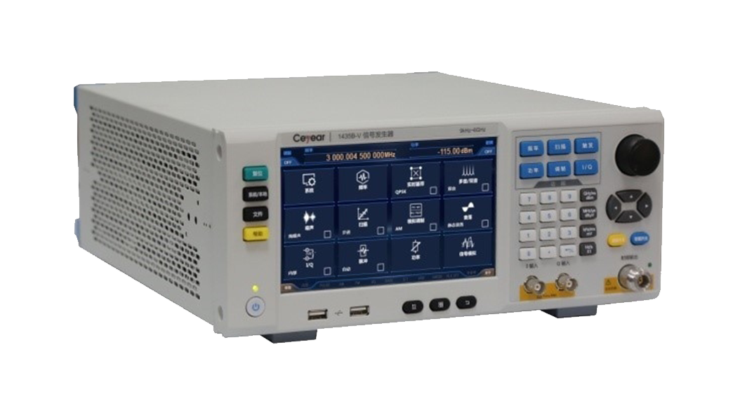
Product Overview
1435-V series signal generator is a vector signal generator with excellent performance, the frequency range covers 9kHz ~ 6GHz, 200MHz internal modulation bandwidth and a full range of digital modulation styles, which can meet the simulation needs of various broadband digital modulation signals. Support 5 download data format arbitrary wave modulation, can be edited according to user needs, download configuration of the required waveforms, to complete a variety of signal simulation, to meet a variety of complex signal testing needs; its baseband signal generator is simple to set up, excellent performance, support for PSK, QAM, FSK, MSK and other more than 20 formats of general-purpose digital modulation signals in real-time generation; with excellent spectral purity. Single-sideband phase noise 1GHz carrier @ 10kHz frequency deviation -136dBc/Hz, 6GHz carrier @ 10kHz frequency deviation -120dBc/Hz; with high power output and large dynamic range, the maximum output power of up to 22dBm @ 3GHz, the dynamic range of the output power is greater than 150dB; with a 7-inch touch-sensitive LED screen, and support for touch-screen, With 7-inch high sensitivity touch LED screen, supporting touch screen, panel buttons, rotary buttons, external mouse and keyboard and other operating modes, the operating experience is fully upgraded; 3U portable chassis structure, small size and light weight, easy to carry. 1435-V in a compact space to achieve excellent performance, not only to meet the equipment R & D stage of the high-performance testing needs, but also to meet the production stage of the high-efficiency testing needs.
